|
(*)
with BONUS PLC Training Course
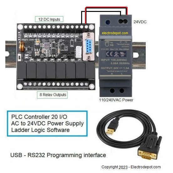
PLC Controller Board Only, RS232 Port
12 DC inputs - 8 Relay Output |
|
|
(*)
with BONUS PLC Training Course
PLC Controller Board Only, RS232 Port
12 DC inputs - 8 Relay Output |
|
|
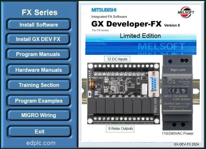
GX-Developer Software |
||||||||
|
|
||||||||
|
e |
|
|
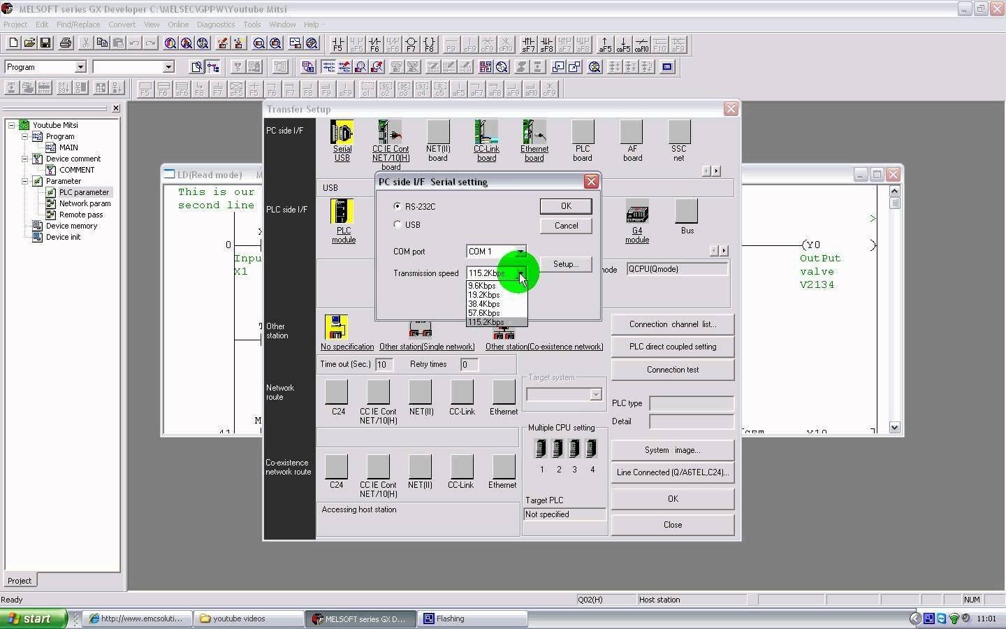
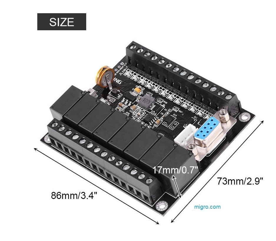
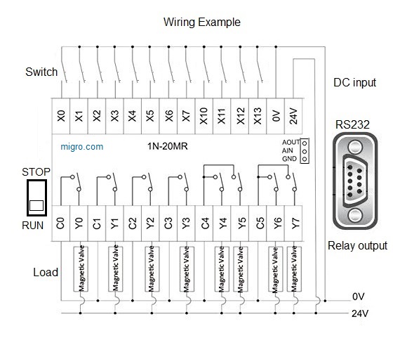
(*) Software 1 - PLC Ladder Logic GX Developer Programming Software GX-DEV FX- 8.25 Open Software CD or USB Flash Drive includes Programming and Hardware Manual Features: 1000 steps Ladder Diagram, and Instruction List Software supports all this FX processors FX0/FX0S, FX0N, FX1S, FX1N, FX(FX2/FX2C) FX2N/FX2NC. FX3u FX MELSEC single user FX Win Version 8.25, 1000 step for FX PLCs controllers series. This is the standard software easy to use and simple, intuitive interface and a short learning curve. Full upload and download, monitor, test and program all the Mitsubishi FX-series PLC package includes CD with the software and manuals in electronic format for programming and hardware installation . 1 - Hardware Features: FX1N-20mr PLC with 12 Inputs and 8 Relay Outputs This programmable logic controller uses industrial-grade 32-bit MCU with strong anti-interference and faster speed. High quality chip, stable performance, on-line download, on-line monitoring, automatic save when power off. Program is written in ladder logic programming language, supports for GX-Developer, GX-work2. Programming port is the port for program upload, download, test and monitor. It is reusable, stable, easy to learn. The PLC transmission baud rate is 9600. Specifications: Model: FX1N-20mr Operating Voltage: DC24(V) Wide Power Supply Voltage: 10-28VDC Baud Rate: 9600 Programming Software: for GX-Developer, for GX-work2. Size: Approx. 86 x 73 x 20mm / 3.4 x 2.9 x 0.7inch Weight: 120G Package Included: 1 x PLC Board Module function: This module is programmable control, can achieve thousands of functions, stable and reliable working performance, built-in watchdog timer circuit, to ensure that the module for a long time to run!!! Some of the common features are shown as follows: Turn on the power supply, the relay 1 is closed for N seconds and then disconnect the relay 2 for N seconds. When the power supply is turned on, the relay 1 is switched off after N seconds, and then the relay 2 is closed for N seconds and then is turned off. The power supply is switched on, the relay 1, 2 have no action, when a signal or trigger button, relay 1 closed off after N seconds; then relay 2 closed off after N seconds, until the next trigger, repeat the same action. Through the signal 1, 2 programming, the control can be achieved on the relay 1 and 2 arbitrarily. When the signal 1 has a signal, the relay 1 is closed, the relay 2 is disconnected; when the signal 2 has a signal, the relay 1 is turned off, and the relay 2 is closed. Can be connected to the NPN sensor signal, the sensor signal programming, to achieve arbitrary control of the relay. When the signal 1 is triggered, the relay 1 is controlled, and when the signal 2 is triggered, the relay 2 is controlled. Turn on the power supply, the control motor is turning N seconds, and then reverse N seconds, followed by the cycle. When the signal 1 has a signal, the motor is controlled to rotate; when the signal 2 has a signal, the motor is reversed. These are just some examples, modules can achieve far more than these functions Input high speed pulse C235, C251 and FX1N compatible. Output relay 1A output, Rated current 5A, can directly drive DC solenoid valve, AC solenoid valve, AC contactor, AC motor, etc,. Precautions for use: The PLC with two programming port. The 232 interface, you can directly use the USB-232 serial port with a computer to download the program directly. The TTL interface. Built-in Analog input AD, corresponding to internal data register D5030.(Not D8030) Built-in Analog output DA, corresponding to internal data register D5101. When the PLC need to connect with the touch screen or text, can be used to connect 232 programming port.
(*) 2 Complete Course Step by Step with PLC programming lessons Easy learning lessons applicable to any Ladder Logic PLC hardware environment Graphic Programming and Simulation, Evaluation at every lesson Table of Contents LESSON 1 ñ Introduction and Overview 1.1 Course Objectives Prerequisites Duration, ------------------------------------1 1.4 Course Description .................................................................................... 2 1.5 Product Line Overview............................................................................... 3 LESSON 2 ñ FX-Series Hardware Review 2.1 What is a dedicated PLC? ......................................................................... 5 2.2 FX Line of PLCs......................................................................................... 6 2.3 Hardware Components .................................................... ................. 8 2.4 Inputs........................................................................... ....................... 10 2.5 Outputs ............................................................... .................................12 2.6 Special Function Modules....................................................................... 14 2.7 High Speed Counter & Positioning Modules............................... .......... 15 2.8 Communication Modules and Option Boards....................................... 17 2.9 Network Modules & Option Boards....................................................... 19 2.10 Miscellaneous ..................................................................................... 21 2.11 Power Supplies.................................................................................... 21 2.12 Exercise ñ Power Supply Calculation ................................................. 29 2.13 Memory Types .................................................................................... 30 LESSON 3 ñ Programming Equipment 3.1 Hand-Held Programming Units ............................................................. 33 3.2 Programming Software .......................................................................... 33 3.3 GX-Developer Overview .........................................................................34 3.4 File Format ..............................................................................................37 3.5 Hardware Connection.............................................................................. 37 LESSON 4 ñ Number Systems 4.1 Binary Numbers ..................................................................................... 39 4.2 Hexadecimal Numbers............................................................................ 40 4.3 Octal Numbers......................................................................................... 41 4.4 Binary Coded Decimal ............................................................................ 42 4.5 Exercise ñ Number Systems Conversion................................................. 43 LESSON 5 ñ Numeric Data in PLCs 5.1 Integer (16/32 Bit) .................................................................................... 45 5.2 Decimal (16/23 Bit) .................................................................................. 47 LESSON 6 ñ System Devices 6. System Devices ....................................................................................... 49 LESSON 7 ñ Addressing 7.1 Right Side Bus Rules of Addressing ....................................................... 53 7.2 FX3U Left Side Bus Addressing ............................................................. 53 7.3 Example................................................................................................... 55 7.4 Exercise ñ PLC Addressing ..................................................................... 56 LESSON 8 ñ Demo Kit Layout 8.1 Addressing............................................................................................... 55 8.2 Indicator Lights ........................................................................................ 56 8.3 Operator Interface.................................................................................... 56 LESSON 9 ñ PLC Instruction Types 9.1 Basic Instructions..................................................................................... 59 9.2 STL (Step Ladder) Instructions ................................................................ 59 9.3 Applied Instructions ................................................................................. 59 LESSON 10 ñ Basic Instructions 10.1 Symbols ................................................................................................... 61 10.2 Ladder Basics .......................................................................................... 62 10.3 Common Instructions ............................................................................... 63 10.4 Exercise ñ Ladder Basics ........................................................................ 65 LESSON 11 ñ Develop and Edit Programs 11.1 Launching GX-Developer......................................................................... 67 11.2 Creating a New Project ............................................................................ 68 11.3 Editing the Ladder.................................................................................... 69 11.4 Program Transfer..................................................................................... 70 11.5 Online Editing .......................................................................................... 71 11.6 Monitor the Program Operation ............................................................... 72 11.7 Forcing Bits and Changing Registers ...................................................... 73 11.8 Exercise ñ Contacts and Coils ................................................................. 73 LESSON 12 ñ Timers and Counters 12.1 Timers...................................................................................................... 75 12.2 Counters ................................................................................................. 76 12.3 Program Examples .................................................................................. 79 12.4 Additional Timer Commands.................................................................... 81 12.5 Exercise ñ Timers and Counters.............................................................. 82 12.6 Exercise ñ Conveyor Control ................................................................... 82 LESSON 13 ñ Applied Instructions 13.1 General Format........................................................................................83 13.2 Data Transfer Instructions....................................................................... 84 13.3 Comparison Instructions ......................................................................... 85 13.4 Exercise ñ Parking Lot ............................................................................ 88 13.5 Exercise ñ Conveyor Control Part 2......................................................... 88 13.6 Conversion Instructions ........................................................................... 88 13.7 Increment and Decrement Instructions .................................................... 89 13.8 Exercise ñ INC and DEC ......................................................................... 89 13.9 Arithmetic Instructions.............................................................................. 89 13.10 Exercise ñ Binary Math.......................................................................... 90 13.11 Exercise ñ Parking Lot Part 2 ................................................................ 90 13.12 Exercise ñ Conveyor Control Part 3....................................................... 90 13.13 High-Speed Processing ......................................................................... 90 13.14 TO/FROM Instructions ........................................................................... 92 13.15 Exercise ñ FX2N-5A Module Access .................................................... 93 13.16 Shift Registers ........................................................................................ 93 13.17 Exercise ñ Bit Shift Register ................................................................... 94 13.18 Program Flow Control ............................................................................ 95 LESSON 14 ñ Diagnostic Devices 14.1 Special M Relays .....................................................................................97 14.2 Special D Registers .................................................................................98 14.3 Handy Troubleshooting Circuits............................................................... 98 14.4 Real Time Clock Usage .......................................................................... 99 14.5 Exercise ñ Daylight Savings Time ......................................................... 100 14.6 GX-Developer Diagnostics..................................................................... 101 14.7 Find/Replace Menu................................................................................ 102 14.8 Data Trace............................................................................................. 107 LESSON 15 ñ Documentation 15.1 ............................................................................................. 109 DISCLAIMER Please Note: We do not provide any type of technical assistance Please contact a Certified professional or a Mitsubishi PLC Specialist Mitsubishi PLC, GX-Developer, GX-work2. are a registered trade marks of Mitsubishi Electric Windows is registered trade mark of Microsoft Corporation Copyright 2024 |